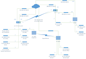
Drawing a Network Diagram
When drawing a network diagram, think about whether it makes sense to draw a logical or a physical diagram. I’d say 90% of the time, a logical diagram is more useful than a physical diagram.
Differences between physical and logical:
- A physical diagram shows you the actual devices involved and the cables that connect them to each other. It should have information about which ports are used what color the cables are, etc.
- A logical diagram will show the types of devices and the subnets in the network. It will not necessarily match up with the physical devices in the network. It should be labeled with the IPs of the subnet and the IP of each device.
If virtual technologies are used, it probably makes sense to note that they are virtual networks or devices, but they should be drawn the same as physical devices.
Once you decide which type of diagram you are making, stick with it. Don’t try to mix and match drawing types. You need to really fight the temptation to put in too much information. Especially information from the other network drawing type.
For example, switches never belong in a logical network drawing. In place of the switch, draw one or more subnets. Conversely, IP numbering doesn’t belong in a physical network drawing. Label the connections with the port name. (e.g. eth0, fa3/1, etc.)

